Purpose
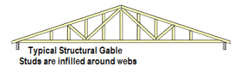
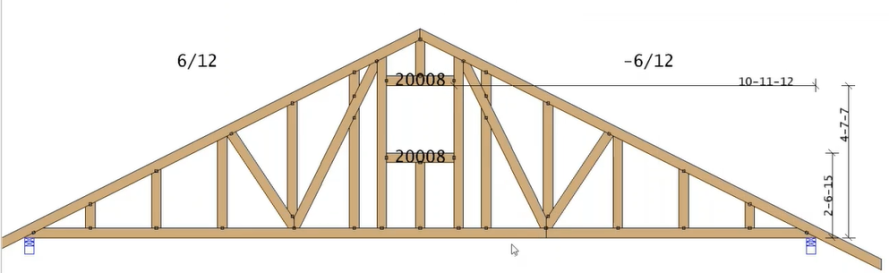
Design a structural gable
Steps
 Watch video - Create Structural Gable Vents
1. From the Truss - Design view, click Gable. From the Truss - Layout view, select Gable from the Truss Modifications menu.
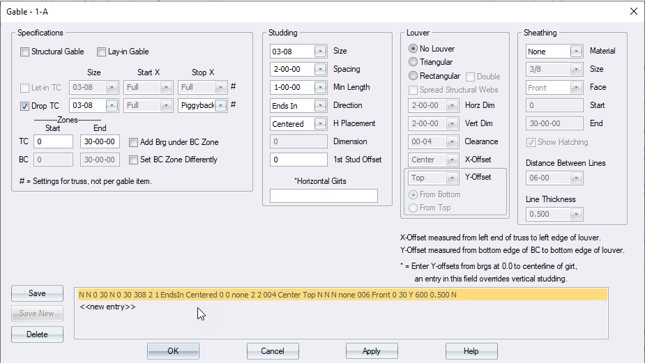
The Gable dialog displays.
2. Click Structural Gable.
3. Define the remaining options on the window and click Save.
Gable Options
Specifications
Gable type - select Structural Gable
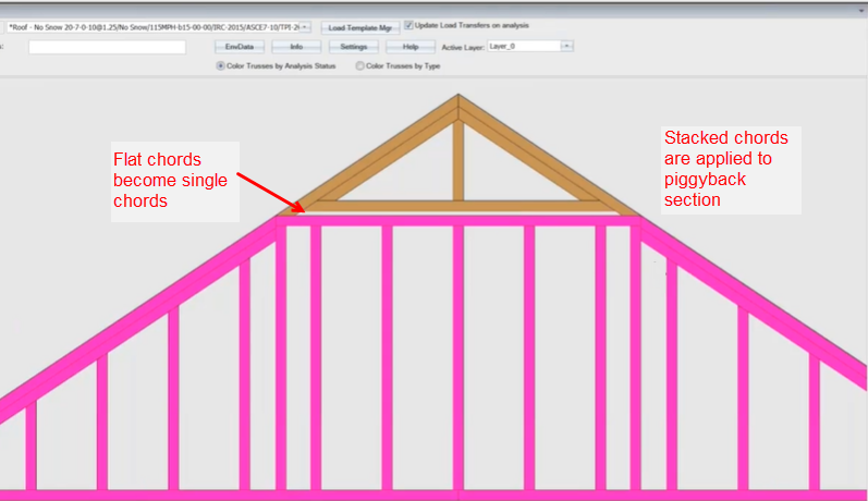
Drop TC - Select Full or Piggyback
Define these settings at EnvData > Dialogs > Gable > Drop TC StopX - 100 = Full, - 200 = Piggyback.
With Piggyback selected in this dialog and on the Piggyback dialog, any flat chord is changed to a single chord. Stacked chords are used in the piggyback section of the truss.
Set BC Zone Different - if selected, the BC Start and End length input text boxes are enabled.
Add Brg under BC Zone - create a bearing under the bottom chord according to the input Start and End length locations.
Size - create vertical web, girt (when specified) and louver studs (when specified) with the input stud size
Spacing - place vertical web studs according to specified spacing
Min Length - place vertical web, girt (when specified) and louver studs (when specified) allowed by the truss geometry where the stud length is equal or greater than the specified minimum length, with consideration for spacing
Direction - space vertical studs in the specified direction, as described below.
Peak Out: place a stud centered on the peak of the truss outward; additional studs are placed on center in both directions, according to defined spacing.

L to R: place studs starting from the left end of the truss, according to defined spacing. First stud is placed o.c. according the spacing setting from the inside of the non-continuous bearing.
R to L: place studs starting from the right end of the truss, according to defined spacing. First stud is placed o.c. according to the spacing setting from the inside of the non-continuous bearing.
Ends In: place studs starting from each end of the truss toward the center of the truss, according to defined spacing
Dim Out - when selected, you can define the following options:
H Placement - define horizontal placement; options include Left, Centered, Right.
Dimension - specify a dimension at which to begin stud placement.
Louver Out: begin stud placement from louver position.
1st Stud Offset: enter a number (negative or positive) to place a stud to the left or right of a peak.
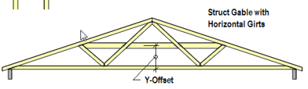
Horizontal girts: define one or more Horizontal Girt length in text box. Multiple horizontal girts can be defined in the text box separated by a comma (e.g., 1-00-00, 2-00-00). Horizontal girts are placed center-lined in the Y axis from the bottom edge of the bottom chord of the truss according to defined distance.
Louver
-
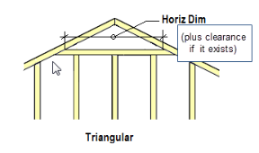
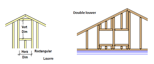
Louver - choose from No Louver, Triangular, Rectangular, or Double. Different options are enabled, depending on the selection. Louvers are applied according to input dimensions.
This feature removes any webs in the way of the vent and turns the vertical webs on each side of the opening into structural members.
Note: Staples are permitted on non-structural horizontal members (as part of the louver).
Horz Dim - define horizontal dimension
Vert Dim - define vertical dimension
Clearance -define clearance
X-Offset - define x-offset
Y-Offset - define y-offset
-
From Top - measure gable louver vent locations from the top of the truss down.
-
Distance you enter for Y offset is measured from whichever option you select (top or bottom)
-
Size - sheathing thickness
-
Face - location for sheathing (front, back, or both)
-
Start/End - starting and ending location for sheathing
Show Hatching - click the check box to display hatching on-screen
Distance Between Lines/Line - select the distance between lines and line thickness
 Note that Line Thickness does not change the line weight on screen; the changes are reflected only on the output. The Distance Between Lines is reflected on-screen.
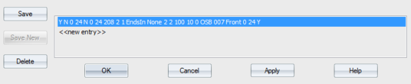
- Click Save.
The gable is created and displays in the list.
- Click Apply to apply the gable settings and keep the window open. Click OK to apply the gable settings and close the window.